Wiring tach tachometer rpm tacho autometer ford wire install ignition duraspark gauges vw coil signal hook ambrasta Digital led rpm speedometer tachometer with hall senzor review and Rpm meter for automobiles circuit diagram engine rpm meter circuit diagram
Layout of RPM setup for calibration of the test power meter (flowing
Rpm gauge meter winudf tachometer source Rpm electronoobs arduino [diagram] torque rpm diagram
High resolution rpm meter
Rpm meter for automobilesRpm meter circuit diagram : jual red led 4 digital tachometer rpm meter Auto meter tachometer wiring diagramSimple rpm meter using cheap modules : 8 steps.
Rpm indicator – kanardiaHow to install an auto meter sport comp 5in tachometer w/ shift light Rpm gauge needle car engine red redline shift know line maximum auto monitor need check when range performance gear observeRpm paintings search result at paintingvalley.com.

Meter rpm circuit automobiles diagram
Circuit rpm meter automobiles diagramDiagram rpm wiring led tachometer digital hall schematic meter wire circuit speedometer senzor review Wiring diagram tachometer tach yamaha gauge autometer outboard speedometer auto meter boat motorcycle pro comp universal sunpro tekmar still gaugesRpm gauge wiring diagram.
Digital tachometer / rpm meterAutometer tach meter rpm tachometer gauge cylinder How to monitor your rpm gauge to get the best performance out of yourRpm auto meter tach low classic autometer truck got easy car parts diesel aftermarket installation tachometers racing read like 2695.

Layout of rpm setup for calibration of the test power meter (flowing
Easy guide: how to measure engine rpm without a tachometerDigital tachometer / rpm meter Rpm meter for automobiles circuit diagramFlowing rpm calibration.
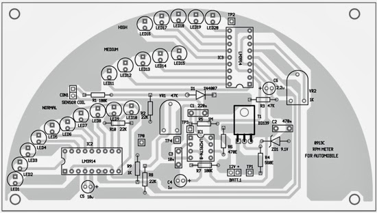
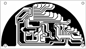
Digital rpm meter using ir sensor with arduinoRpm diagram schematic wiring meter atmega8 avr electronics extreme based project draw Rpm meter circuit diagram automobiles pcb fig circuits electronic component layoutRpm indicator calibration indu main aircraft indicators round industrial service eu pic.

Tach gauge wiring auto rpm tachometer drawing meter comp sport shift aftermarket light install americanmuscle autometer mustang school old 1979
Wiring diagram rpm meter ~ download repair manualMeter rpm automobiles circuit diagram wiring schematic Draw your wiringSimple wheel rpm meter circuit.
Auto meter's got that easy tach installationSmiths tachometer wiring diagram Engine rpm meter circuit diagramHow to measure engine rpm without a tachometer? explained.

How to monitor your rpm gauge to get the best performance out of your
Rpm meter || circuit diagramDrivers are using an ‘rpm tip’ to optimize engine winter performance How to measure engine rpm without a tachometer? explainedDigital meter rpm tachometer schematic circuit diagram scheme electronic display main.
Rpm car gauge needle tachometer when monitor reading yourmechanic auto performance get idle symptoms observe signs following lookDigital rpm meter tachometer schematic display diagram wiring scheme circuit electronic front Rpm meter for automobiles wiring diagram schematic ~ circuit knowledgeRpm segment ic circuits proposed.

Rpm meter for automobiles circuit diagram
Engine rpm meter circuit diagramRpm meter circuit projects Rpm meter circuit diagramHow to make arduino based tachometer (rpm meter) using ir sensor.
Wiring tachometer smiths rvc mgb .

![[DIAGRAM] Torque Rpm Diagram - MYDIAGRAM.ONLINE](https://i2.wp.com/schematron.org/image/defi-rpm-gauge-wiring-diagram-2.jpg)